1. Introduction
A (Direct-On-Line) DOL Starter is one of the simplest and most widely used motor starters for three-phase induction motors. It directly connects the motor terminals to the full line voltage, allowing the motor to start immediately at its rated voltage.
This type of starter is ideal for small-capacity motors (up to 5 HP), where the inrush current, although high, does not cause significant voltage drops in the system.
The DOL starter is preferred in industrial, agricultural, and domestic applications for its simplicity, reliability, and cost-effectiveness. Despite its limitations for large motors, it remains the first choice for compact, low-power motor systems.
We will go through following:
2. What is a DOL Starter?
A DOL Starter is an electrical control and protection device that allows direct connection of a three-phase induction motor to the power supply without any intermediate voltage reduction. It facilitates both starting and stopping operations and provides overload protection.
When switched ON, the starter applies full line voltage to the motor terminals. The motor thus experiences a high starting current—approximately 6 to 8 times its full-load current—but develops a high starting torque simultaneously.
For this reason, DOL starters are not used for motors exceeding 5 HP (3.7 kW), as excessive current draw could affect the supply network and cause mechanical stress.
3. DOL Starter Circuit Diagram
Below is a standard representation of a DOL starter circuit:
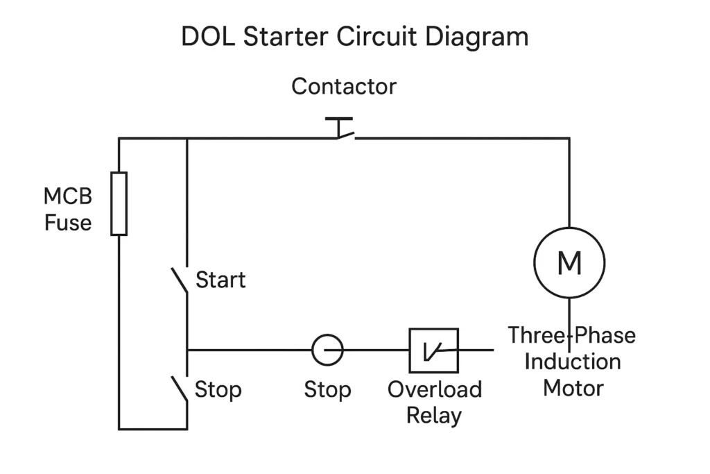
3.1 Circuit Explanation
The DOL starter circuit consists of two main sections:
- Power Circuit – Connects the three-phase supply to the motor through the contactor and overload relay.
- Control Circuit – Includes the push buttons (START and STOP), contactor coil, and overload relay contacts used to control motor operation.
Sequence of Operation:
- The Start push button energizes the contactor coil.
- The contactor closes, connecting the motor directly to the supply line.
- The Overload Relay remains in series with the motor, monitoring current flow.
- When the Stop button is pressed or overload occurs, the circuit opens, de-energizing the contactor and disconnecting the motor.
4. Working Principle of DOL Starter
The working principle of a DOL starter is simple: it directly connects the motor terminals to the full line voltage through a contactor. When the start button is pressed, the contactor closes, allowing full voltage to reach the motor and produce high starting torque. Once the motor reaches its rated speed, it runs at normal current. The overload relay monitors the current and disconnects the circuit in case of overload, ensuring motor protection.
Press Start Button:
The start button energizes the contactor coil through the control circuit.
The contactor closes its main contacts and auxiliary holding contact, maintaining supply continuity even when the button is released.
Motor Starts:
The motor now receives full supply voltage (usually 415 V in three-phase systems).
The motor begins to rotate, drawing high starting current for a few seconds until it reaches the rated speed.
Running Condition:
Once running, the motor current reduces to its normal operating value.
The overload relay remains active to monitor for excessive current.
Press Stop Button:
The control circuit opens, de-energizing the contactor coil.
The contactor opens the power circuit, disconnecting the motor completely.
Overload Protection:
If motor current exceeds the pre-set value, the overload relay trips automatically, protecting the motor from overheating.
This simple principle makes DOL starters highly dependable for low-power motor control systems.
5. Main Components of DOL Starter
A DOL starter is composed of a combination of protective, control, and switching devices. Each component plays a crucial role in ensuring safe and efficient motor operation.
5.1 Miniature Circuit Breaker (MCB) or Fuse
- Protects the circuit from short circuits and fault currents.
- Interrupts the power supply in case of abnormal fault conditions.
5.2 Contactor
- An electromagnetic switch used to connect or disconnect the motor from the power supply.
- Operated by a control coil that responds to the start/stop commands.
- The contactor carries the main current and is designed to handle both inrush and steady-state current.
5.3 Overload Relay
- Protects the motor from overcurrent due to overload conditions.
- Operates on the thermal principle—when current exceeds the limit, it heats a bimetallic strip that trips the relay.
- Automatically disconnects the contactor, preventing motor damage.
5.4 Start Push Button
- A normally open (NO) switch that energizes the contactor coil when pressed.
- Used to initiate motor operation.
5.5 Stop Push Button
- A normally closed (NC) switch.
- When pressed, it breaks the control circuit, de-energizing the contactor and stopping the motor.
5.6 Three-Phase Induction Motor
- The load device controlled by the DOL starter.
- Operates on electromagnetic induction principles and is the most common motor type in industrial use.
6. How to Make a DOL Starter Yourself
Constructing a simple DOL starter can be a valuable practical project for electrical engineering students and technicians. Below is a step-by-step guide to build a functional unit.
6.1 Tools and Materials Required
- 3-Phase Supply (415 V AC)
- Contactor with 3 poles and a 230 V coil
- Thermal Overload Relay (current rating matching the motor)
- MCB or fuse unit
- Start and Stop push buttons
- Wires, terminals, and mounting panel
- Three-phase induction motor (up to 5 HP)
6.2 Circuit Connection Steps
- Mount the Components:
- Fix the MCB, contactor, overload relay, and push buttons on a panel board.
- Ensure proper insulation and spacing between connections.
- Power Circuit Wiring:
- Connect the three-phase supply from the MCB output to the contactor input.
- From the contactor output, connect the lines to the Overload Relay, and finally to the motor terminals.
- Control Circuit Wiring:
- Take one phase and neutral for the control supply.
- Connect the Stop button (NC) in series, followed by the Start button (NO), and finally to the contactor coil terminal.
- Connect an auxiliary contact of the contactor across the Start button for latching (holding contact).
- Overload Protection Integration:
- Wire the overload relay’s normally closed contact in series with the control circuit.
- This ensures the contactor de-energizes if an overload condition occurs.
- Testing the Setup:
- Switch ON the MCB.
- Press the Start button; the contactor should pull in and motor should start.
- Press Stop; the motor should stop immediately.
- Simulate overload to test trip function.
6.3 Safety Precautions
- Always perform wiring with power OFF.
- Verify insulation resistance before operation.
- Never bypass the overload relay.
- Use components rated appropriately for the motor capacity.
This simple DOL starter can be used for small motors in workshops or for educational demonstrations.
7. Advantages of DOL Starter
- Simplicity:
Easy to install, operate, and maintain. - Low Cost:
Inexpensive compared to reduced-voltage starters. - Compact Design:
Requires minimal space and wiring. - Reliable Operation:
Fewer components mean fewer chances of failure. - Provides Overload Protection:
Protects the motor under overload conditions.
8. Disadvantages of DOL Starter
- High Starting Current:
Draws 6 to 8 times the full-load current during startup. - Voltage Drop:
May cause line voltage fluctuations affecting nearby equipment. - Mechanical Stress:
Sudden torque can damage shafts and couplings. - Not Suitable for Large Motors:
Used only for motors below 5 HP.
9. Applications of DOL Starter
The DOL starter is extensively used in light industrial and domestic motor applications where simplicity and economy are essential. Some common examples include:
- Water Pumps and Borewells
- Air Compressors
- Blowers and Fans
- Conveyor Belts
- Small Lathes and Milling Machines
- Centrifugal Machines
- Mixers and Grinders
- Agricultural Equipment
Its robust design ensures consistent performance in variable field conditions.
10. How to Convert DOL Starter to Star Delta Starter (Short Answer)
To convert a DOL starter to a Star-Delta Starter, follow these essential modifications:
- Add Two More Contactors:
- One for star connection and one for delta connection.
- Add a Timer Relay:
- To switch automatically from star to delta after a preset time (usually 5–10 seconds).
- Reconfigure the Motor Terminals:
- Ensure six terminals of the motor are accessible for star/delta connection.
- Modify Control Circuit:
- Include interlocks to prevent simultaneous star and delta contactor operation.
Result:
At startup, the motor runs in star configuration (reduced voltage), then automatically switches to delta (full voltage) once it reaches 80% of its speed—significantly reducing the starting current.
11. Maintenance and Troubleshooting Tips
- Regularly Inspect Contacts: Clean or replace if pitted or burnt.
- Check Overload Relay Settings: Match with motor’s rated current.
- Ensure Proper Tightening: Loose terminals cause arcing and heat.
- Test Start/Stop Buttons Periodically: Faulty push buttons can cause control failures.
- Monitor Coil Voltage: Under/over voltage can affect contactor operation.
- Keep Circuit Dry and Dust-Free: To prevent short circuits and corrosion.
12. Key Differences Between DOL and Star Delta Starter
| Parameter | DOL Starter | Star-Delta Starter |
|---|---|---|
| Starting Method | Direct connection to supply | Starts in star, then shifts to delta |
| Starting Current | 6–8 times full-load current | 2–3 times full-load current |
| Starting Torque | High | Moderate |
| Components Required | Simple (1 contactor, 1 relay) | Complex (3 contactors, timer relay) |
| Cost | Low | High |
| Suitable Motor Rating | Up to 5 HP | Above 5 HP |
| Voltage Drop | High | Low |
| Maintenance | Easy | Moderate |
13. Conclusion
A DOL Starter (Direct-On-Line Starter) represents the most fundamental and reliable method of starting three-phase induction motors. Its straightforward design, cost efficiency, and protective features make it indispensable for small motor systems in both industrial and domestic environments.
However, for larger motors, alternative starters such as Star-Delta, Autotransformer, or Soft Starters are recommended to limit inrush current and protect the electrical system.
In summary, a DOL starter provides an excellent blend of simplicity, durability, and performance — making it a vital component of motor control technology and an essential topic in every electrical engineer’s learning journey.
Q1. Why does a DOL Starter draw 6 to 8 times the full-load current during startup?
Because the motor is directly connected to the full line voltage without any starting resistance or impedance. At standstill, the rotor frequency equals the supply frequency, resulting in very low impedance and high inrush current until the motor gains speed and back EMF reduces the current.
Q2. How does the overload relay in a DOL Starter protect the motor?
The overload relay operates on the thermal principle. When current exceeds the preset value, it heats a bimetallic strip inside the relay, causing it to bend and open the control circuit. This action de-energizes the contactor, disconnecting the motor and preventing overheating or winding damage.
Q3. What happens if the Start button of a DOL Starter is released immediately after pressing?
Once the Start button is pressed, the contactor closes and its auxiliary holding contact keeps the circuit energized even after the button is released. Therefore, the motor continues running until the Stop button is pressed or an overload condition occurs.
Q4. Can a DOL Starter be automated without manual push buttons?
Yes. By integrating sensors, timers, or PLC-based control circuits, a DOL starter can be automated to start or stop motors based on parameters such as water level, temperature, or process conditions—while retaining overload protection through the relay.
Q5. Why is a DOL Starter preferred for agricultural water pumps?
Because such installations usually operate small motors (below 5 HP) and are located in areas with simple electrical setups. DOL starters provide direct, quick starting with minimal components, ensuring easy field maintenance and dependable operation even in harsh environments.
Q6. How does the contactor ensure both electrical and mechanical interlocking?
The contactor not only completes the electrical path between the supply and the motor but also provides mechanical interlocking through spring-loaded contacts. When de-energized, the contactor automatically opens to isolate the motor, ensuring safe operation during faults or maintenance
Q7. What could cause a DOL Starter to trip frequently under normal load?
Frequent tripping may occur if the overload relay setting is too low, supply voltage is unstable, or motor bearings are worn, leading to excess current draw. It may also indicate incorrect relay calibration or poor ventilation causing excessive thermal buildup.
Q8. How does the DOL Starter affect the mechanical parts of the motor?
The high starting torque of a DOL starter exerts a sudden mechanical shock on shafts, couplings, and belts. Over time, this can lead to wear and fatigue. Hence, periodic inspection and alignment are recommended for motors frequently started and stopped using DOL starters.
Q9. Why is the DOL Starter called the simplest form of motor starter?
Because it directly connects the motor to the line voltage without intermediate components like resistors, transformers, or autotransformers. It uses only a contactor, overload relay, and push buttons, which makes it straightforward in both design and operation.
Q10. Can a DOL Starter be used with single-phase motors?
Technically, DOL starters are designed for three-phase induction motors. However, modified single-phase DOL-type starters exist that use a single-pole contactor, thermal overload relay, and capacitor control for small single-phase motors like fans or compressors.