on this page
What is rankine cycle?
The Rankine cycle is one of the most important thermodynamic cycles in power generation. It serves as the foundation of nearly all steam-based power plants, from coal-fired stations to nuclear, geothermal, and solar thermal facilities. If you’ve ever wondered how the heat from burning fuel, splitting atoms, or even sunlight gets transformed into the electricity that powers homes and industries, the Rankine cycle is at the heart of that process.
This article provides a complete, problem-solving explanation. Whether you’re a student preparing for an exam, an engineer refreshing your knowledge, or simply curious about energy systems, you will find clear definitions, detailed processes, diagrams, efficiency formulas, types, and real-world applications—all in one place.
Definition of Rankine Cycle according to engineering books
The Rankine cycle is a thermodynamic cycle that converts heat energy into mechanical work using a working fluid that undergoes phase change (typically water and steam). It is the idealized cycle for steam power plants, consisting of four processes:
- Isentropic compression in a pump,
- Constant-pressure heat addition in a boiler,
- Isentropic expansion in a turbine, and
- Constant-pressure heat rejection in a condenser.
This closed-loop design makes the cycle repeatable and efficient. While the real-world version has some inefficiencies, the Rankine cycle provides the idealized model that engineers use as the basis for designing and optimizing steam power plants.
Also Read:
Thermal power plant: Definition, Working, components, Drawing
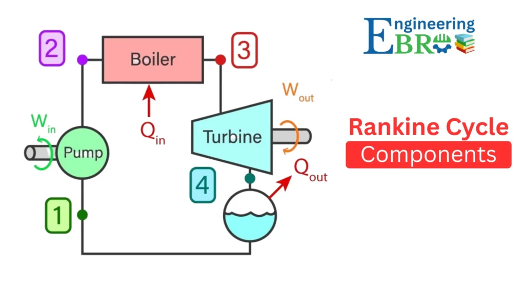
Components of the Rankine Cycle
Let’s break down the four major components and their roles:
a) Boiler
- Function: Converts pressurized water into steam by supplying heat from an external source such as coal, oil, natural gas, nuclear fission, geothermal reservoirs, or concentrated solar energy.
- Process type: Isobaric (constant pressure).
b) Turbine
- Function: Converts the thermal energy of steam into mechanical work by allowing it to expand and rotate the turbine blades. This mechanical work then drives an electric generator.
- Process type: Isentropic expansion (ideally no entropy change).
c) Condenser
- Function: Cools and condenses the exhaust steam from the turbine back into liquid water by rejecting heat to a cooling medium (river water, seawater, or cooling towers).
- Process type: Isobaric heat rejection.
d) Pump
- Function: Increases the pressure of the condensate so it can re-enter the boiler. Though the pump consumes some work, it is small compared to the work produced by the turbine.
- Process type: Isentropic compression.
Processes of the Rankine Cycle
The cycle involves four distinct thermodynamic processes, usually represented as 1–2–3–4 on diagrams:
- Isentropic Compression (1 → 2)
- Water at low pressure is pumped to boiler pressure.
- Work is done on the fluid (small compared to turbine output).
- Isobaric Heat Addition (2 → 3)
- High-pressure water absorbs heat at constant pressure in the boiler.
- It turns into saturated or superheated steam.
- Isentropic Expansion (3 → 4)
- Steam expands through the turbine, producing shaft work.
- Temperature and pressure drop during this expansion.
- Isobaric Heat Rejection (4 → 1)
- Exhaust steam enters the condenser and is cooled at constant pressure.
- It releases latent heat and condenses back into liquid water.
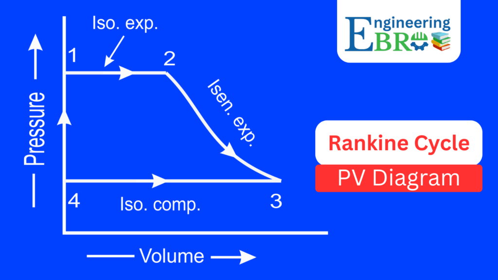
Rankine cycle P-V Diagram
The Pressure–Volume (P–V) diagram represents pressure changes against volume:
- 1 → 2 (Isobaric heat addition in boiler):
Pressure remains constant while the fluid volume increases drastically as water turns into steam. - 2 → 3 (Isentropic expansion in turbine):
Pressure drops significantly as steam expands through the turbine. Volume increases. - 3 → 4 (Isobaric heat rejection in condenser):
At constant pressure, steam condenses back to water, leading to a large reduction in volume. - 4 → 1 (Isentropic compression in pump):
Water volume changes very little but pressure increases greatly.
The P-V diagram highlights the pressure drops and volume changes, showing how much expansion work is obtained from the turbine.
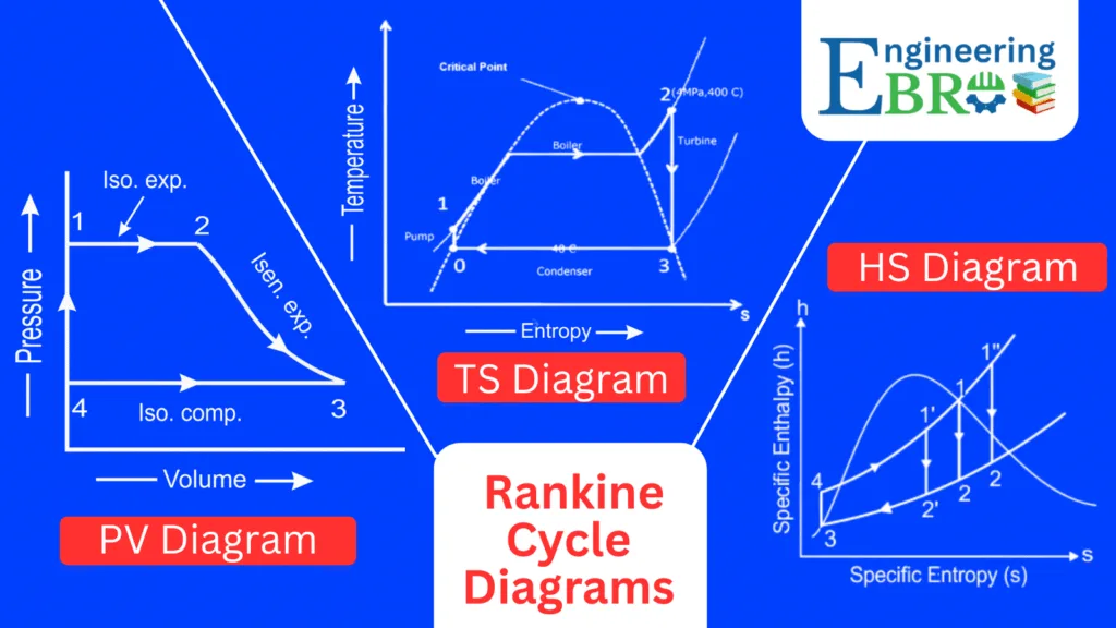
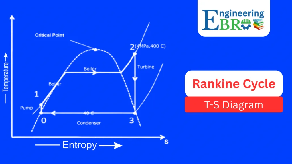
Rankine cycle T-S Diagram
The Temperature–Entropy (T–S) diagram is the most widely used representation:
- 0 → 1 (Pump process – Isentropic compression):
The working fluid (water) at low pressure is pumped to boiler pressure. Since pumping is nearly isentropic, entropy remains almost constant. The temperature rises slightly. - 1 → 2 (Boiler heating – Isobaric heat addition):
At constant pressure, heat is added in the boiler. Water turns into saturated steam and then superheated steam (point 2 at high temperature and entropy). - 2 → 3 (Turbine expansion – Isentropic expansion):
Steam expands in the turbine, doing work. Temperature and pressure drop, but ideally entropy remains constant. - 3 → 0 (Condenser – Isobaric heat rejection):
Steam is condensed at constant pressure into liquid water, rejecting heat to the cooling water. Entropy decreases as heat leaves the system.
The area enclosed by the cycle on the T-S diagram equals the net work output of the cycle. This makes it particularly useful for efficiency analysis.
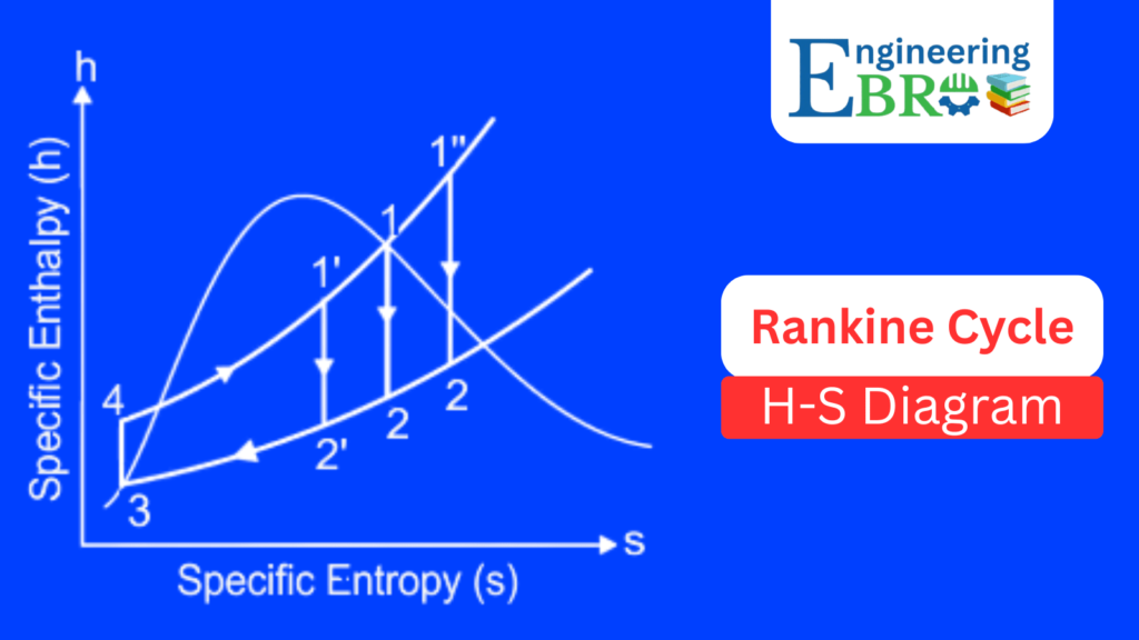
Rankine cycle H-S Diagram (Mollier Diagram)
The Enthalpy–Entropy (H–S) diagram, also called the Mollier diagram, is especially useful for steam turbine calculations:
- 1 → 2: Represents compression in the pump (slight increase in enthalpy).
- 2 → 2′ (Heating in boiler): Heat addition raises enthalpy, and the fluid becomes superheated steam.
- 2′ → 3 (Expansion in turbine): Almost vertical drop (isentropic expansion). Enthalpy decreases significantly while producing turbine work.
- 3 → 4 (Condensation): Heat rejection lowers enthalpy, steam condenses back to water.
It is often used in practical power plant operations since enthalpy values are directly linked to energy balances.
Rankine cycle efficiency formula
The thermal efficiency of the Rankine cycle expresses how much of the heat input is converted into useful work. This is also known as the Rankine cycle efficiency formula.
= [ (h3 − h4) − (h2 − h1) ] / (h3 − h2)
Where h1…h4 are the specific enthalpies at points 1–4 in the Rankine cycle.
Typical Efficiency Range
- Subcritical Rankine cycle: 30–38%
- Supercritical & advanced Rankine cycle: 40–46%+
- Nuclear Rankine cycle: 30–33%
Key Factors Affecting Efficiency
Efficiency depends on turbine inlet temperature and pressure, condenser pressure, and cycle modifications (reheat, regeneration, supercritical operation).
Types of Rankine Cycle
To overcome efficiency limits, engineers developed several modifications:
- Simple Rankine Cycle – Basic four processes.
- Reheat Rankine Cycle – Steam expands in two stages with reheating in between. Prevents moisture in turbines and improves efficiency.
- Regenerative Rankine Cycle – Uses feedwater heaters that extract steam from the turbine to preheat boiler water, raising efficiency.
- Supercritical Rankine Cycle – Operates above the critical point of water (374 °C, 22.1 MPa). No distinct phase change, higher efficiency.
- Organic Rankine Cycle (ORC) – Uses organic fluids (like hydrocarbons or refrigerants) with lower boiling points, suitable for low-temperature heat sources such as geothermal and waste heat recovery.
Applications of Rankine Cycle
The Rankine cycle is applied across many industries:
- Thermal Power Plants – Coal, oil, and natural gas-fired.
- Nuclear Power Plants – Steam produced by nuclear reactors drives turbines.
- Marine Propulsion – Steam turbines in naval ships and submarines.
- Geothermal Power Plants – Steam from underground reservoirs is used directly.
- Concentrated Solar Power (CSP) – Solar heat creates steam for turbines.
- Industrial Cogeneration Systems – Combined electricity and process heat generation.
Advantages
- Simple and widely understood.
- Proven reliability for large-scale power generation.
- Flexible with multiple heat sources.
- Can be enhanced with reheat, regeneration, and supercritical operation.
Limitations
- Efficiency capped around 45% in practical systems.
- Requires large and costly equipment (boilers, condensers).
- Needs a large amount of cooling water.
- Environmental impact from fossil-fuel-fired versions (emissions, thermal pollution).
Strategies for Improving Efficiency
Engineers often face the challenge of improving efficiency and reducing costs. Some proven methods include:
- Superheating steam to higher temperatures.
- Reheating steam after partial expansion.
- Regenerative heating of feedwater.
- Operating at supercritical pressures.
- Using alternative working fluids (organic Rankine cycles).
- Hybrid systems – integrating Rankine cycles with gas turbines (combined cycles).
Case Studies and Real-World Examples
- India’s coal plants: Most operate on subcritical Rankine cycles, with efficiencies around 35%. Newer supercritical units achieve above 40%.
- Nuclear plants: Use Rankine cycles with saturated steam for safety, typically 30–33% efficiency.
- Geothermal plants: Often adopt ORC cycles due to lower reservoir temperatures.
- Solar thermal plants: Use modified Rankine cycles with thermal energy storage to ensure power supply even after sunset.
Frequently Asked Questions
1) Why is the Rankine cycle more commonly used than the Carnot cycle in power plants?
The Carnot cycle is ideal but not practical because it requires isothermal heat transfer, which is very difficult to achieve in real systems. The Rankine-cycle, on the other hand, is more practical, easier to implement, and better suited for steam power plants.
2. What is the difference between a simple Rankine cycle and a regenerative Rankine cycle?
In a simple Rankine-cycle, steam is expanded in a turbine without preheating the feedwater. In a regenerative Rankine-cycle, part of the steam is extracted to heat the feedwater before it enters the boiler, which improves efficiency.
3. Why is reheating used in the Rankine cycle?
Reheating prevents steam from becoming too wet during expansion in the turbine. This improves turbine blade life, reduces erosion, and increases cycle efficiency.
4. How does the condenser improve the Rankine cycle?
The condenser condenses steam into water at low pressure. This reduces the back pressure on the turbine, allowing more work extraction, and provides a closed-loop system by supplying water back to the boiler.
5. Can the Rankine cycle work with fluids other than water?
Yes. Variants like the Organic Rankine-Cycle (ORC) use organic fluids with lower boiling points, making them suitable for low-temperature heat sources such as geothermal, solar thermal, or industrial waste heat.
6. What limits the efficiency of the Rankine cycle?
The efficiency is mainly limited by the maximum temperature and pressure that the materials in the boiler
Conclusion
ThIS cycle is more than just a theoretical concept—it is the backbone of modern electricity generation. From coal and nuclear to solar and geothermal power, its applications span across industries and continents.